
Working Principle of Pellet Mill and Pellet Plant
EQUIPMENT USED WITHIN A PELLET PLANT
The Pelletizing System
The pelletizing system is composed of several different machines, such as pellet mill, hammer mill, mixer and cooler, designed to most efficiently accomplish the pelletizing task. A typical system arrangement with equipment names is shown in Kingman product list. While more detailed information relative to the function of each machine can be found in their detailed introduction, it would be advisable to first learn the names and relationships of these major processes.
Before feedstock is mixed and before going to the pellet mill it should go through a sieve (or called sifter or screener). This removes everything such as metal (ferrous and non-ferrous), stones, string, paper, wood blocks, chips, material lumps and gives a dressed feedstock into the bin above the pellet mill. A pellet mill is not designed to pellet these materials, let alone the combustion of them. The pelletizing process starts with a surge bin (which actually happen to be a buffer stabilizing the work of pellet mill) in which the mixture of raw material is stored. From there, the feedstock will flow into the pellet mill. After being pelletized, hot extruded biomass (pellets) will be conveyed into a cooler where it is held for three to six minutes while being cooled and dried by counterflow of air. The air is drawn through the mass of pellets and passed into a dust collecting device, such as a cyclone collector. The dust from the outlet of the collector can be designed to return to the pellet mill be compacted again into pellets.
After the above, a sieve or shaker is demanded to sift pellets from mealy material. The shaker separates the product into various sizes by passing the material over several screens. Each screen is of a different opening size. This separation permits the desired product to be separated from the larger or smaller particles while being delivered to the finished product bin via elevator, the vertical conveyer. The “overs” through the sieve can be returned to the pellet mill for repelletization. The fines or smaller material can be routed directly back to the pellet premix bin and reprocessed through the pelletizing system. Alternatively, it can also be collected manually according to the requests from clients who may have the intention of reducing investment in equipment.
Supply Bins
The supply bin (surge bin or called a buffer) or bins must be adequate to store a sufficient quantity of feedstock immediately ahead of the pellet mill to provide not only continuous operation of the pelletizing unit but also continuous operation of the mixer which provides material to the pelletizing unit. Other factors in a pellet mill design may dictate a need for greater available tonnage ahead of the pellet mill. Generally speaking, the bin supply immediately ahead of the pellet mill should hold a relatively large capacity of the pre-pelletizing mixer used to supply feedstock to the pelletizing unit. A bin installation of this type will usually result in an efficient operation, both from a mixing and pelletizing standpoint, and is the minimum. The maximum will be determined by factors other than the pelletizing installation.

The surge bin should be constructed so that there will be no bridging or surging. Variations in the feedstock cause objectionable variations in the operation of the pellet mill. Generally, the bin can best be constructed of sheet metal. And round bin is commonly put into use.
Pellet Mills
Mixed feedstock will be allowed to flow by gravity into a flow rate regulator called a “feeder”. The feeder is generally a screw-type with some variation in flight arrangement, such as single flight, double flight, full pitch or one-half pitch to accommodate varying conditions. It is equipped with some type of speed control, such as a variable speed electric drive. The purpose of the feeder is to provide a constant, controlled and even flow of feed to the mixing and pelletizing operation. Any variation in this flow results in poor conditioning and a variable product.
This feeder delivers a constant and prescribed amount of feedstock to a “conditioning” chamber. Here material is second-time mixed for a better mixing effect prior to entering pellet mill. A mixer is provided in order to properly condition feedstock. Uniform conditions at this point are extremely important for optimum results.
The conditioned mash then flows by gravity into the pellet mill die chamber where rollers press the softened material through the holes in a circular die.
Stationary knives located outside the circular, rotating die cut off the shaped dense pellets at the proper length.
Most modern pellet mills used a ring type die turning about two fixed rollers, with the die and rollers mounted in a vertical plane. A few pellet mills are built with the dies and rollers in a horizontal plane with the rollers turning within the stationary die. Obviously there are advantages to each type of construction but more pellet mills made today are of the vertical type.
In the pelletizing unit, the conditioned material is forced through holes in the die by roller pressure.
Die thickness is a factor in the production of high quality pellets and must be accurately balanced with the formulation and conditioning. Starting with 6mm pellets and above, some variation in the amount and depth of taper incorporated into the entry of the holes in the die may be necessary.
All pellet mills incorporate some type of speed reduction device, since die speeds are always less than the conventional motor speeds. In some cases variation in die speed is desirable to produce optimum results on individual groups of biomass material. Speed reduction devices in use today include direct coupled gear trains, V-belts, cog belts and combinations of belts and gear trains.
Currently, pellet mills are being built with speed change mechanisms. Usually these speed change mechanisms are in the form of gear shifts or two-speed motors. This provides two die speeds to secure optimum results when a wide range of feedstock is produced.

Most pellet mills are installed with an electric motor as the prime mover; however, internal combustion engines are sometimes used. When internal combustion engines are used the horsepower rating should be at least twice that of the electric motor normally used. The pellet mill and motor are usually mounted on a common base to maintain alignment of the pellet mill and motor and to provide a rapid, simple and efficient method of installing the equipment.
Although it is not a part of the pellet mill, an ammeter should be included as part of the electrical system. This will allow the operator to adjust the feed rate to secure the maximum capacity of the pellet mill without overloading the motor.
Pelletizing Dies
Considerable attention must also be given to the various types of dies used by pellet mill manufacturing industry. Die thickness and hole size varies with the type of product to be pelletized as stated previously. Relieved dies have an enlarged diameter on the discharge side of the hole. Relief length is the distance of the die hole which has a greater diameter than the rest of the hole.
There are basically four types of dies available:
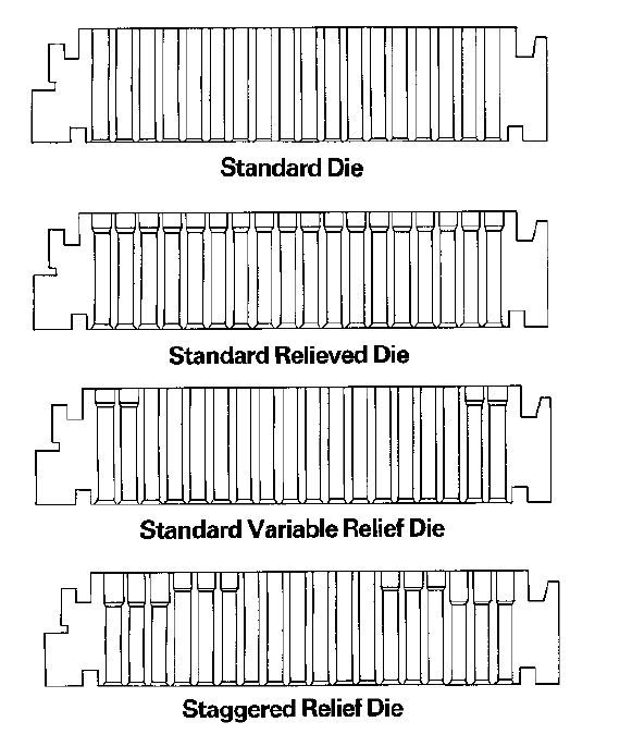
Standard Die---All the holes have the same effective thickness.
Standard Relieved Die---All holes have the same effective thickness, but the discharge side of the hole is enlarged. The primary purpose for this die is to add strength to the die without making the hole depth thicker.
Standard Variable Relief Die---All holes are the same except the two or three outside rows of the die. The number of rows to be relieved varies by die manufacturer. Certain products to be pelletized will have a tendency to squeeze out to the side of the die. When this happens the two or three outside rows become plugged and as much as 25% of the die effectiveness is lost.
Staggered Relief Die---This die basically serves the function as the standard variable relief die except that the two or three outside rows are relieved 1/2?and the next two or three rows are relieved.
Coolers
From pellet mill chamber, pellets normally flow by gravity into a conveyer for cooling and drying. Pellets will leave the pellet mill at temperatures as high as 80 to 90 degrees centigrade and moisture contents are high as 17-18%. For proper storage and handling of the pellets, their moisture content must be reduced to 10-12% and their temperature to about 5 degrees higher than the atmospheric temperature. This is to be accomplished by passing a stream of air through a bed of pellets. This evaporates the excess moisture, causing cooling both by the evaporation of water and by contact with the air. Air doubles its capacity to hold water with every 20° rise in temperature. In other words, the warmer the air the more moisture it should remove from the processed pellets.
The operation and construction of a typical vertical cooler is simple. Pellets flow (usually by gravity) from the pellet mill to the funnel-shaped hopper on top of the cooler. Pellets resting in this hopper act as an air seal that forces the cooling air to pass through the cooling chamber to reach the fan. When the amount of pellets in the chamber reaches the level sensing device it starts the discharge gate drive motor which turns the discharge gates at the bottom of each column, thereby lowering the level of pellets in the cooler to accommodate the continuous flow of hot pellets from previous pellet mill. While the flow of pellets through the columns is being automatically related to exactly the production rate of the pellet mill, fan is drawing air into the air plenum chamber, discharging this mealy dust laden air to a cyclone “dust” collector.
During a production run, an accumulation of dust may build up in the dust collector connected with the cooler plenum chamber directly. A pellet plant may adopt pulse dust collector or manually tapped one, the two of which are different just in prices but the pulse dust collector is more automatically convenient.
Pellet Elevating Systems
The correct sized product from a sieve is now in its finished form and ready for packaging or shipment. In many pellet plants, pellet shaker is placed on the upper floors of the structure to permit the screened product, the oversize crumbles and the fines to flow by gravity to their correct destination. This requires that the unscreened pellets be conveyed vertically (elevated) from the cooler to the sieve. In other cases the sifter is placed below the cooler and the sized finished product is conveyed to the packaging or bulk shipping point. In either case, an elevating system (vertical conveyor) is usually required. This can be done mechanically by means of a bucket elevator (also called a “leg) or it can be done pneumatically by an air conveying system. Air systems are sometimes used to convey hot pellets because they are not as subject to the buildup of hot, wet material as is a bucket elevator. Usually bucket elevators are used because they are less expensive to install, maintain and operate.
Pelletizing
The real heart of the pelletizing process is the nip point or the area where the wedge of feed is between the roll and the die within a pellet mill. Most all other equipment in the pelletizing process is supportive equipment to this, the most crucial part of pelletizing.

There are three points of pressure: (1) the roll acting upon the material compresses the material into the die, (2) the die itself has a resistance that can hold back the flow of the material through the holes in that die, and (3) the pressure exerted by the rolls combined with the frictional pressures of the formulation itself. This pressure keeps the material compressed together and keeps it from squirting along the face of the die in front of the roll.
When we increase the variable speed drive or control and increase the amount of feedstock into pellet mill, the amount of feedstock thickens in direct proportion just in front of the roll. In other words, there is greater force pushing the feedstock into the nip point instead of down into the holes of the die. This is normally what causes a pellet mill to plug. This slug or mat of feedstock can build up in front of the roll, hindering the roll’s ability to crimp and push feedstock into the die holes. Thus, surges of feedstock should be prevented from entering into the pelletizing chamber.
Feedstock distribution is extremely important across the face of the die and into this nip point. Feed distribution is a problem and can cause the pad to be too deep and, again, limit the ability of the roll to force the product into the die holes. This essentially limits the production. This is why it is critical that the rolls be set on a regular basis, remembering that the feed flow through the die is what causes the die to wear away from the rolls. The rolls should be adjusted to a point so that the roll will be allowed to turn.
Pelletizing is a daily exercise in ability and knowledge. While large pieces of equipment are necessary to complete the pelletizing process, it should become obvious at this point that the operator is, unquestionably, the most important factor in achieving a good pellet production and good pellet quality. He must understand the pelletizing process and be able to adjust many times in a particular day to the ambient temperatures, humidity, formulation changes, conditions of ingredients, and bound or inbound moisture levels of these ingredients. Running a pellet mill can be a trying, difficult process or one of great challenge for the individual. It becomes basically his choice as to which he prefers.
Densification technologies provide practical options for overcoming some of the inherent drawbacks of biomass (moisture content and low energy density being the most important). Pelletizing can be regarding as one of the well established densification procedure, gaining increasing popularity and acceptance in recent years. This is primarily due to pellets dimensions (appropriate for automatic feeding), durability and consistent and standardized quality. However, it is noteworthy that actual process can differ from ones depicted, since it highly depends on kind of the raw material to be used, planned investment and available land for plant set up.
As a Chinese pellet mill manufacturer, KMEC has been in a leading position of pellet mill supply and large pellet turnkey project contract. Our product has been exported to many foreign countries like American, German and Malaysia and so on. To make the best pellet mills is our only mission. We welcomes client from all around the world to consult and cooperate with us in the future.
--------------------------------------------------------------------------------------------------------------------------------------------------------
News
- Small Pellet Machine Manufacturer-Kingman
- Application of Wood Pellets and Use of Biomass Pellets
- From Fossil Fuel into Biomass Pellet Fuel
- Biomass Pellet Making Machines Market
- Applying of pellet stoves for home use
- Highland pellets to build $130 million facility in arkansas
- How to deal with the blocked hammer mill
- How to Make Wood Pellets with Sawdust
- The government policy promotes the development of biomass fuel
- Market analysis of biomass pellet fuel
- Strategic positioning of renewable energy
- Biomass energy has pass through the pre assessment
- The key point of deep processing of biomass pellet
- Harbin is promoting the development of biomass machinery
- The development of biomass formation technology I
- The development of biomass formation technology II
- Biomass energy industry is now going full tilt in 2015
- Rapid increasing demand of sawdust pellet on the market
- Pellet fuel market in EU
- Chinese Biomass Energy Conference held in Beijing
- Future market development of straw pellet mill
- Peanut Shell Pellet Mill Makes High Quality Pellets
- The utilization of straw is only 5%, biomass energy needs our attention!
- Corn straw pellet machine relieves the tight supply of fuel energy
- Reasons for loose or not forming of biomass pellet mill


")

